Hi All,
Excuse me for writing in English but its maybe the most compatible option ![]()
Personally I am not happy with sticking Lipo cells out in the nature, all it will take is one fire!! As a result have been developing a multi-chemistry MPPT solar charger with a personal preference for LTO mainly for its cold weather charging abilities. While there are a couple of solutions to be found on the internet to address this need, one seems to be no longer available, one is great but binds you to a RAK module and the aliexpress one is, I would say, incomplete. They are all based on the CN3795 as is this one.
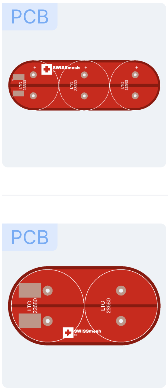
I have produced my own PCB inspired by the great work of Vlastimil Slinták who makes the Solar mesh baseboard but my wish was for a “charger only” PCB.
So far I have made two prototype batches of 5 units in iterations. The first one did not include an onboard regulator, the second one adds an efficient onboard regulator with a solder jumper to select between 3.3V and 5V output and an option to disable the regulator completely. Note that the regulator will shutdown at around 1.2V but requires 1.8V to startup again which is mainly relevant to LTO. Output ripple was measure at 25mV.
Both units have been tested and work as designed. I am now preparing for a larger production run with a few additional changes to the previous two prototypes.
These would come with pre-defined resistor values for LTO, Sodium-ion and LifePO4 1S configurations, you just need to solder the jumper.
Solar panel Vmp voltages by default for 9V, 12V and around 18V panels, 7.5V input voltage is the minimum possible with this charger.
Max charge current is configurable in steps with a max current of 1.2A and other options at 120mAh, 483mAh and 847mAh
For the battery charge voltage and the Vmp voltage (MPPT) there is a place to solder your own through hole resistor to set a custom value for your needs.
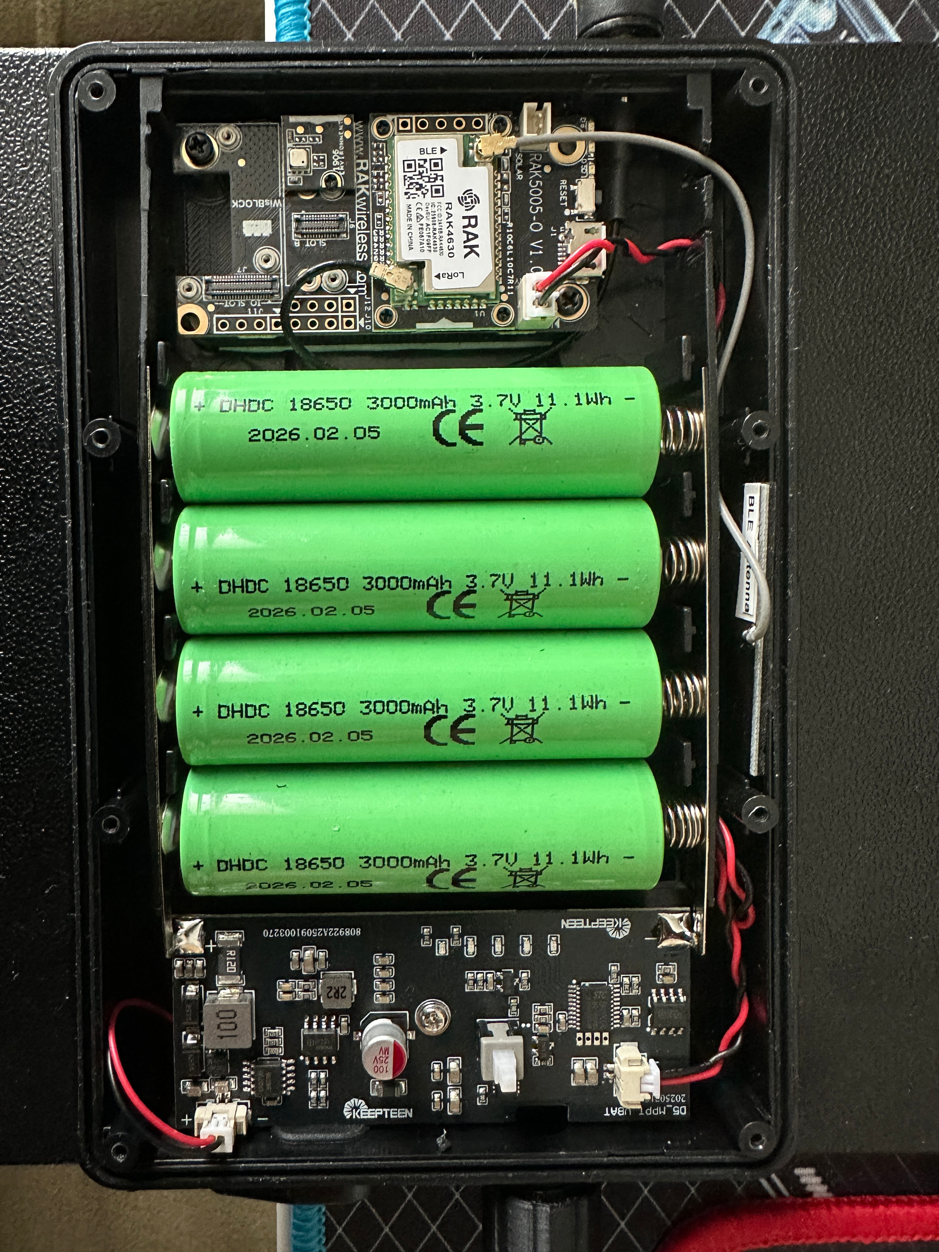
I have been testing with a 9V panel of 147mm x 147mm and achieving around 260mAh in ideal conditions using an LTO cell. Example setup
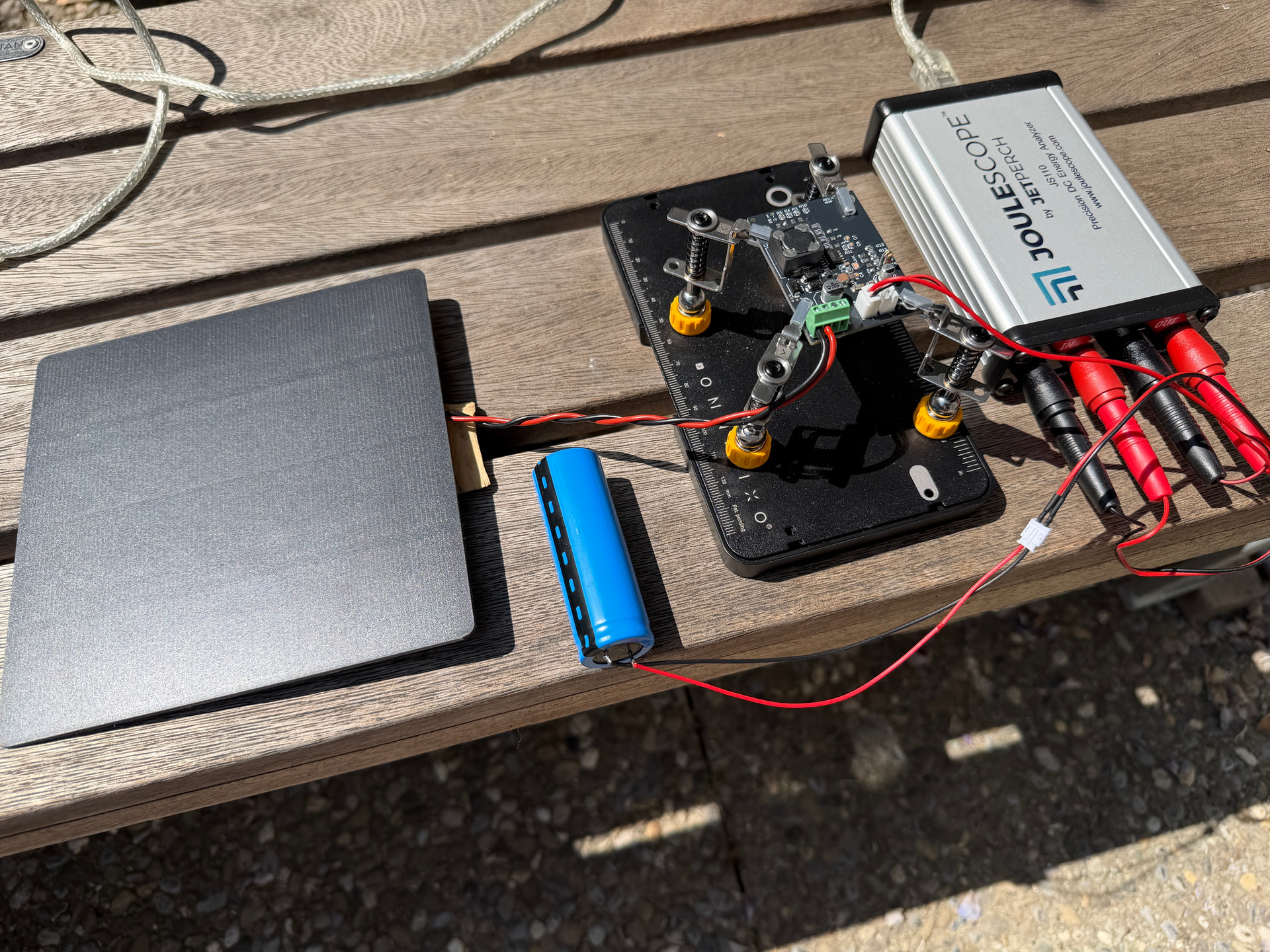
Now I am reaching out to see if there is any interest from the Mesh community so I can size my first production run accordingly and additionally to understand if there are any other ideas I have not covered. I am not attempting to make any money with this but simply trying to cover my costs and a bit of time, the sales price would be roughly 30.00 CHF plus shipping.
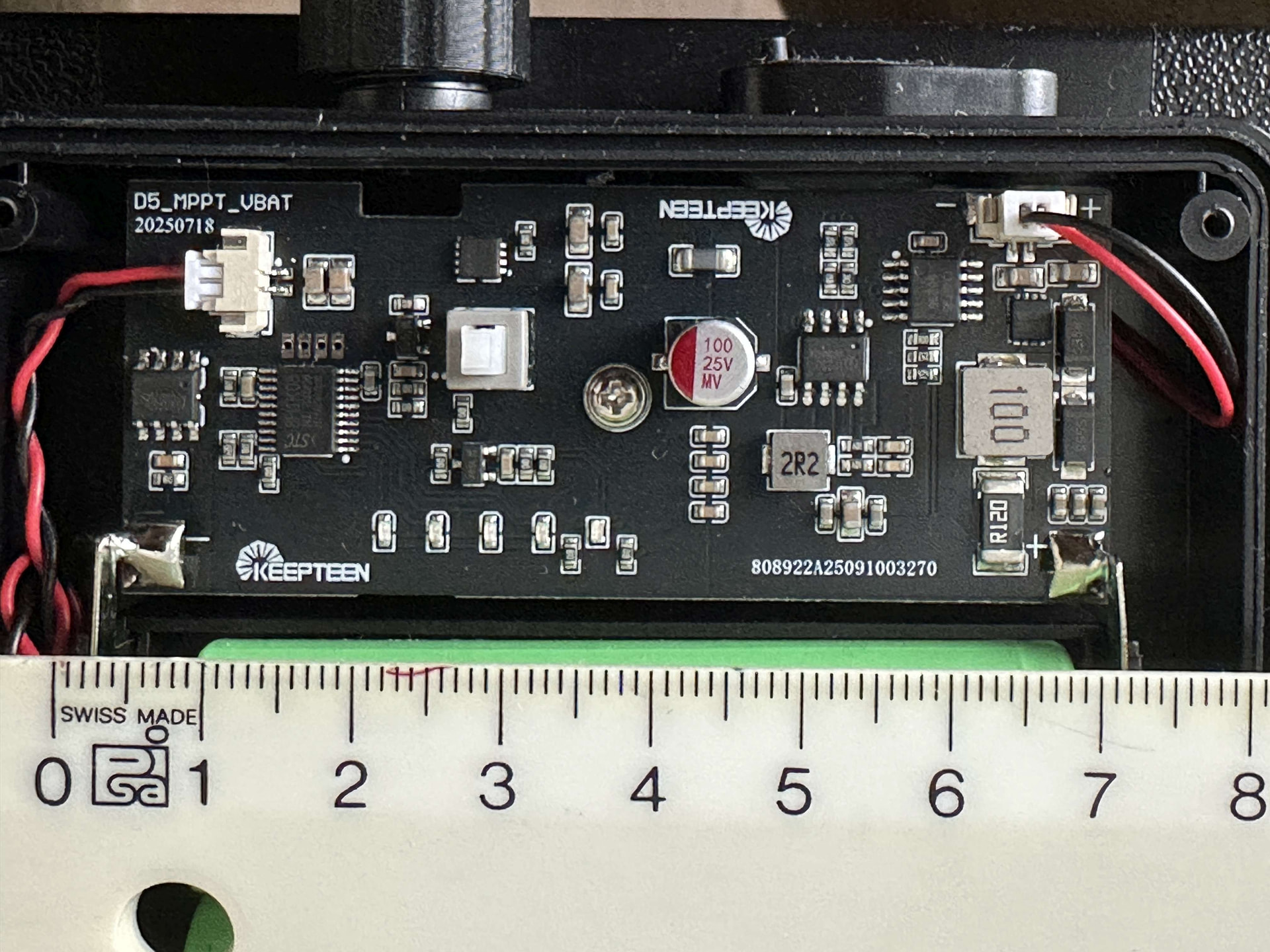
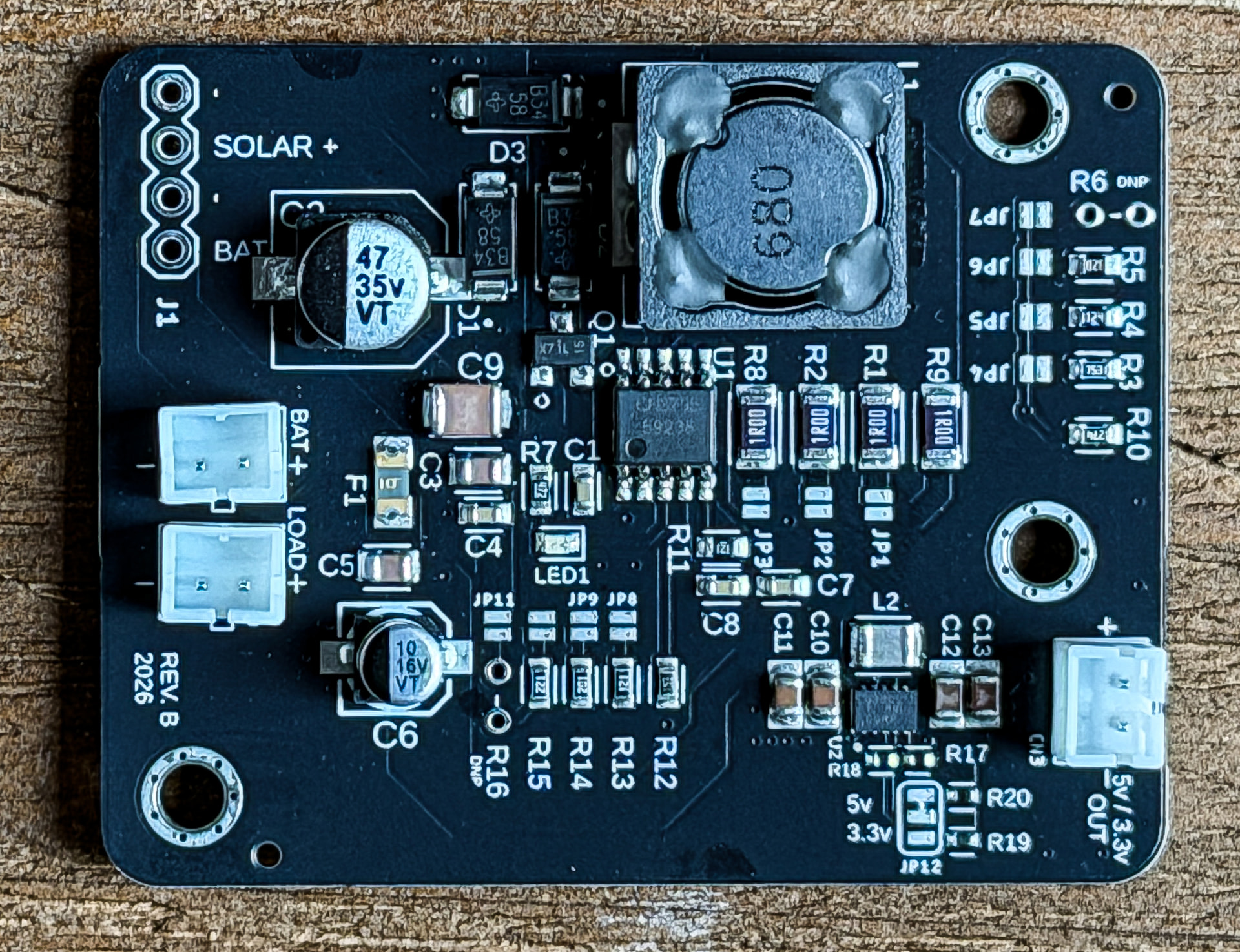
Here is a picture of the pre production unit. The final one will not have two battery connectors. i.e. the “Load” connector will be removed but raw battery is still available at the 4 pin header J1.
PCB size is 52mm X 41mm ± 2mm
I do have 2-3 pre-production units immediately available. 10.00 CHF for the one without the regulator and 15.00 CHF with the regulator + shipping cost.
These test units have slightly different defaults for 1S LTO, 2S LTO and 1S Na-ion and 120mAh, 240mAh, 360mAh and 480mAh charging currents but if you tell me your needs I can add resistors to set the battery charge voltage and Vmp.
P.S. I also have a LTO 1S BMS coming in the form factor of an 18650 cell for easy integration with a 2-5P pack of cells. It will expose an I2C interface using a QWIIC connector for battery voltage and power consumption, compatible with an INA260 so it works in Meschore without any changes. Again it is based on the open source work of Vlastimil, its his engineering, I have simply taken a different approach to form factor and re-designed the PCB accordingly. I will have the first prototypes in a week or two.
Thanks,
Serge
# Spec. sheet below
Solar Charger Section
High-efficiency buck switching controller with hardware-configurable presets.
1. MPPT Configuration (Solar Panel Optimization)
*Sets the Maximum Power Point floor *
| Jumper | Resistor | Target Voltage | Typical Use Case |
|---|---|---|---|
| JP8 | 90.9k | 9.01V | Standard 9V/12V Panels |
| JP9 | 120k | 11.35V | High-Voltage 12V Panels |
| JP10 | 200k | 17.77V | Standard 18V Panels |
| JP11 | DNP | Custom | Through-hole pads for custom panels |
2. Charge Voltage Configuration (Chemistry Select)
Sets termination voltage
| Jumper | Resistor | Target Voltage | Battery Chemistry |
|---|---|---|---|
| JP4 | 133k | 3.65V | 1S LiFePO4 |
| JP5 | 205k | 2.80V | 1S Sodium-ion (SIB) |
| JP6 | 290k | 2.33V | 1S Lithium Titanate (LTO) |
| JP7 | DNP | Custom | Through-hole pads for custom voltage |
3. Charge Current Selection (1206 Shunt Bank)
Parallel resistor bank for thermal stability (Base 1.0R is always active).
| Jumpers Closed | Total Resistance | Charge Current | Mode |
|---|---|---|---|
| None | 1.0R | 120mA | Safety / Trickle |
| JP1 | 0.248R | 480mA | Standard Charge |
| JP2 | 0.142R | 840mA | High-Power |
| JP1+JP2+JP3 | 0.099R | 1.21A | Turbo Mode |
System Output Regulator (TPS63802)
High-efficiency synchronous buck-boost converter providing a stabilized system rail.
1. Operational Limits
- Safe Input Voltage: 1.8V to 5.0V Maximum (Optimized for 1S packs)
- Continuous Output Current: 2.0A
- Peak Switching Current: 4.5A
- Function: Seamlessly transitions between buck and boost modes to maintain regulation even as battery voltage drops.
⠀2. Output Voltage Selection (JP12)
- Jumper Open: 3.3V (Optimized for ESP32, nRF, and low-power MCUs)
- Jumper Closed: 5.0V (Standard USB-level sensors and peripherals)
⠀3. Disable jumper (JP13)
- Cut JP13 to disable the built-in regulator, J1 provides solar input and raw battery output
⠀